Servicing Alarm Systems Requires Knowledge, Patience and Technique.
Servicing Alarm Systems – Alarm systems are simple, robust and reliable but their longevity also means there are large numbers of security systems that are well into their 30s and some are older still. Troubleshooting these old systems, as well as recent traditional control panels, requires plenty of care.
There are specific trouble shooting procedures that can be employed when working with alarm systems. Starting at the beginning, this means we’ll be focusing on volts, ohms and milliamps. Modern digital multimeters combine the VOM functions with neat things like amps, capacitance, transistor testing, continuity and/or diode testing.

To be systematic you must plan. It’s a worthwhile exercise making a simple diagram of a system soon as you get onto a site. If there’s not a basic schematic taped into the panel box wander round and make one.
So – we’re on site and we’ve drawn up a simple plan – keypad at the front door, 3 PIRs (living room, hallway, main bedroom) two reed switches (front and back door), and 1 PIR and 2 reeds looped on a single zone protecting a rumpus room. There’s also separate siren and strobe outputs. By this time, we’ve also looked the system over and made the assumption that there’s nothing obvious wrong.
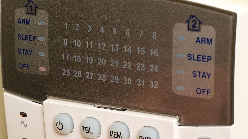
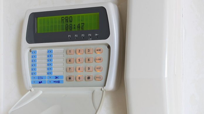
Just to make things easier let’s introduce a concrete scenario. Servicing Alarm Systems-This alarm system has a permanent trouble. Be aware that most modern alarm panels have self-diagnostics. You walk in through the front door and the keypad will indicate trouble on a particular zone. Some older LED panels offer similar diagnostic reporting. Depending on configuration they’ll flash loop or sensor trouble on zones, or they might flash the ‘ready’ if there’s trouble with the communicator.
That doesn’t always happen, of course, and not all older panels are capable of the same level of fault reporting – older models may have little fault reporting at all. You must have your installer manuals with you to assess a diagnosis correctly unless you’re very experienced with a particular control panel.
Having established there’s no obvious fault with the system, the first step is to establish where the problem lies. Is it in the control panel or in the zone? Your actions will depend on system configuration as well as the age of the system. Are all detection devices on a single loop or does each have a separate zone? Do all zones carry a single device except the 2 reed switches and 1 PIR in zone 2? Jot your findings down before moving on.
In the old days there was a simple way to check the zone integrity at the controller end on closed loop zones. You just removed both wires from the zone input and ran a jumper across the terminals. As far as the controller was concerned the system was secure and armed and if an installer removed one of those jumper wires, the system would go into alarm.
It’s more complicated these days with EOLs used to make a loop that’s protected by application of the correct resistance. Happily for the troubleshooter, you can use an EOL to create a virtual protected loop. You connect the 2.2k EOL till it connects with the relevant zone terminal and the shared common terminal and you’ve effectively got a protected loop. If you undertake this procedure during troubleshooting of an unprotected loop and the zone works, chances are you’ve got a sensor, connection or loop problem.
If the problems persist, it will be a controller fault. You can test the controller’s response by removing one side of the EOL from the zone terminal, or by shorting the loop, and seeing if the system goes into alarm. If there’s a controller problem, these actions may not be detected by the panel.
Checking all the zones at the panel is a fiddle but is easy enough. Depending on the protective loop configuration, work your way across the zone inputs, Z1 and shared C (zone 1 and shared common), then on the right of the common, Z2 and C (zone 2 and shared common). Depending on technique and requirements, you’ll be using the same single 2.2k EOL resistance on each set of inputs.
Take into account that the procedure varies depending on the sort of protective loops that are built into system. A single closed loop will require you to disconnect both loop wires, to add jumpers (or an EOL) across the terminals and to trip the system by lifting the jumper or EOL wire. But a double closed loop with no ground will require both +in and +out be removed and replaced by +in to +out and -in to -out. All will depend on the sort of protective loops the system contains.
Servicing Alarm Systems – Checking Zone Loops
Have your multimeter/VOM switched to voltmeter for this one. Let’s say that as you worked your way across the zone inputs no fault was found with the controller, but Zone 2, to which loop were attached 1 PIR and 2 Reed switches protecting a rumpus room and 2 french doors was unusual. The controller behaved perfectly when tested with the EOL and the permanent trouble went away.
The next step is to establish what kind of fault it is you’re facing. Is it a foreign potential, a ground, a short, or an open? Probably the strangest and potentially most damaging to the system is the presence of a foreign potential (voltage) on the loop. Happily, it’s also the least likely problem you’ll encounter.
When you use the voltmeter to check a loop what you’re measuring is current on a wire so it’s important to establish whether the system has a voltage on its zone loops when disarmed. Some old systems won’t have power when disarmed and in these instances you can either use as ohmmeter or continuity tester (both have built-in power) or disconnect the siren and strobe outputs and test the system when it’s armed.
At this point, check for power across battery terminals and for power across loop terminals. Remove the connecting wires to each zone and replace them with the voltmeter’s connections. If the right voltage is present, assume that the trouble lies with the loop. Again, complexity is introduced to troubleshooting depending on the zone loop.
Servicing Alarm Systems
In simple closed loop systems things are easier because anything in the loop causing an alarm must be an open contact. But if it’s a double closed loop then an alarm could be the result of an open in one wire, an open in a second wire, or a short between two wires. It could even be the result of a ground on the hot wire if the loop has one side grounded permanently.
For the sake of this discussion let’s assume that the loop containing the PIR and 2 reeds is closed and the 3 devices are connected to a cable run about 21m long with the devices spread out at 7m intervals.
Go to the middle of the cable run between the first PIR and the first reed. If there’s appropriate voltage at that point, then the system is good to that point. Now go past the first reed. If the system remains good, then you know the failure lies on the other side of the first reed and is caused by either the second reed switch or cabling or its terminations.
Servicing Alarm Systems- Another technique when testing loops while servicing alarm systems is to place the voltmeter leads over the terminals of each device. What you’re looking for here is voltage and if you find it then you’ve found your open contact. This is a simpler method, but it has weaknesses. For a start this method won’t indicate broken wires and nor will it be useful if there’s more than just 1 open contact in the loop.
You can see the latest alarm systems at SecTech Roadshow (pre-register here) or read more news from SEN here.
“Servicing Alarm Systems Requires Knowledge, Patience and Technique.”


