Current drain can be a major nuisance with alarm systems as it robs systems of the ability to operate properly, lead to either false alarms or inoperability.
When checking current in the circuit you always want to avoid letting your test equipment have an impact on the circuit. Connect the meter onto the non-earth supply lead or find the system’s on/off switch and connect your multimeter across this, taking care to use the correct polarity.
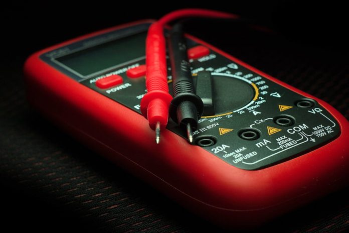
Adjust your DMM to high current range. If the system is dis-armed you’re likely to measure slightly higher current across the switch than you would if the circuit was under load – you can adjust your test unit downwards for greater accuracy if lower currents are registered. Should you find any excessive current flow you’ll have found the source of your problem and will know something, somewhere in the circuit is chewing current. Importantly, you’ll also have located a potential point of overheating.
Many installers and technicians will immediately begin carrying out continuity checks at this point but it’s better practice to start with a thorough physical examination of the circuit. Nothing more may be required than cleaning off excess flux that has formed itself into a blob between supply rail circuit tracks or poor connections – anything that’s going to lead to a short circuit. A physical examination can be made more easily and accurately using a magnifying glass.
If your search for a physical explanation draws a blank, then it’s time to start continuity testing. You can either employ a dedicated continuity tester or use your DMM set to resistance range (it’s not as effective). The lowest resistance range should be your choice. What you don’t want is for your test equipment to display continuity between 2 points that have a small but still significant resistance between them.
Bear in mind here that the use of low resistance ranges is going to employ major test currents. Even a test current of 150-200mA is going to pose a threat to semiconductors and other delicate components. The last thing you want your test process to cause is new faults on the circuit through damage to components.
#securityelectronicsandnetworks.com


