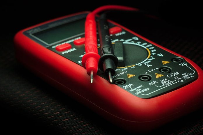
Could SEN explain the operation of the potential divider in a digital voltmeter? What does this circuitry do?
A: A digital voltmeter has 2 key components – these include a digital module and a potential divider section. Analogue input voltages arriving at the digital module’s inputs are converted and displayed on an LED screen. But there’s a limit to the maximum voltage the digital module can tolerate. It’s the potential dividers’ job to reduce the input voltage to a level that can be accepted by the digital module.
In essence this divider is a series circuit in which a voltage is applied to an entire resistance network upon which a switch decides on a take-off point for the voltage to be handed over to the digital module. When the potential divider is designed, resistors are selected that break the voltage down so it can be applied to each of the necessary ranges covered by the voltmeter. As a rule, regardless of the voltage range you select on the meter, the resistance between the unit’s input terminals remains identical to the total resistance of the voltmeter’s network, typically 10 ohms.
#sen.news


