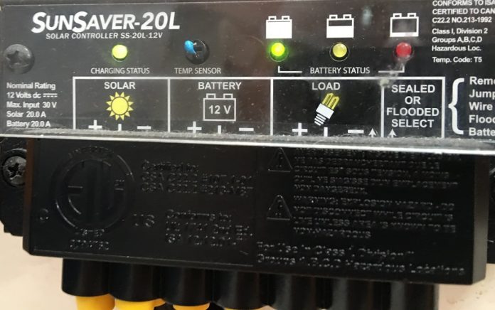
We are upgrading a solar powered CCTV, access control and alarm solution installed in a remote outbuilding on a property in Queensland – we’ve upgraded the panels from 2x 100-watt to 2 x 160-watt but have run into trouble.
The new panels are within the existing controller’s specifications, with an output of less than 20A and a voltage of less than 30V. While the upgraded panels worked fine initially, the Sunsaver 20L is now no longer charging the batteries, despite the fact there’s a bit more than 20V at the inputs. During daytime we see a heartbeat LED that flashes green once every 5 seconds.
The battery LED is not displaying at all. We’ve checked the positive and negative fuses between the controller and the battery and they are fine. Do we need a new controller, or do we need to upgrade this controller to a higher amperage? Staff are currently charging the batteries with a petrol generator every few days. What’s your advice?
A: The Sunsaver 20L has comprehensive status reporting via LEDs. The status signal you are observing – one green flash every 5 seconds – indicates night mode. Day mode is represented by a solid green signal flashing off every 5 seconds (as pictured above). Exceeding peak solar voltage or current is indicated by different signals, so those possibilities can be discounted.
Not being able to see your wiring makes this a bit harder but it sounds like a fuse has blown on the hot side of the solar input between controller and battery bank – aside from covering the panels during the day, this is the only thing that could cause the Sunsaver 20L to signal night mode when in full sun with normal voltage (around 20.3V DC) measured across the solar inputs.
Replacing 200 watts of solar with 320 watts, you’ve gone from an average of 8-12A to an average of 12-16A and if the existing input fuse is rated to 15A it will have blown on the first sunny day after the upgrade. The 2 fuses you’ve checked are almost certainly the load.
You’ll need to dig around and find the red fuse case on left hand input side – trace the positive wire from solar positive to battery – it should be closer to the battery than the controller. While you’re replacing the solar input fuse, change the load fuse – it should match the maximum load for this controller – 20A.
*Field tech has confirmed the issue was a blown 15A fuse. Replaced with 20A, system now working as it should!
#sen.news


